

When building multiple-service sites, our combiner/diplexer techniques can minimize feeder cables without hampering the performance. Ace Technologies’s low PIM RF products guarantee operator’s maximum performance in constructing more-complicated frequency systems in addition to offering optimal DC/AISG port solutions to customer’s installation conditions.
-
-
-
Low insertion loss -
-
Low PIMD performance
-
-
-
-
3GPP/AISG compatible -
-
Compact size -
-
IP 67
-
-
AVT-AISGF-DB15-20.0M
1. Protocol AISG 2.0/AISG 1.1 Material Plating 2. Rated Voltage V DC 250 Housing Die Cast Nickel 3. Insulation Resistance (min) MΩ 500 Dielectric Thermoplastic 4. Contact 0.25 mm2 MΩ 0.0000876 Contact Plating Silver/gold Resistance 0.75 mm2 MΩ 0.000028 Wire Guage UL2464 Cable 5. Current Rating (at 40° C) A 5 6. Characteristic Impedance Ω 100±20 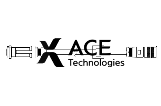
-
AVT-AISGF-DB15-10.0M
1. Protocol --- AISG 2.0/AISG 1.1 Material Plating 2. Rated Voltage V DC 250 Housing Die Cast Nickel 3. Insulation Resistance (min) MΩ 500 Dielectric Thermoplastic --- 4. Contact 0.25 mm2 MΩ 0.0000876 Contact Plating --- Silver/gold Resistance 0.75 mm2 MΩ 0.000028 Wire Guage UL2464 Cable --- 5. Current Rating (at 40° C) A 5 6. Characteristic Impedance Ω 100±20 -
AVT-AISGF-DB9-20.0M
1. Protocol --- AISG2.0/AISG1.1 2. Rated Voltage (max) V 300 Pin Material QSn6.5-0.1Y Gold 3. Rated Impulse Withstand V 1000 Pin Insulator PBT553 (Black) --- 4V.oIlntasguelation Resistance (min) MΩ 500 Connector Body Brass Nickel (3μm) 5. Contact Resistance (Max) MΩ 5 Wire Gauge UL2464 Cable, Black PU --- 6. Current Rating (at 40° C) A 5 7. Test Voltage V AC 670 8. Characteristic Impedance Ω 100 ± 20 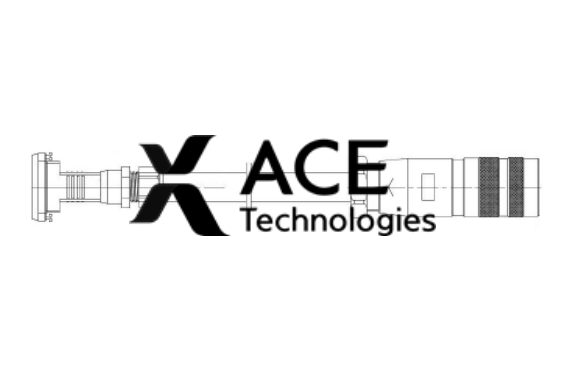
-
AVT-AISGF-DB9-10.0M
1. Protocol --- AISG2.0/AISG1.1 2. Rated Voltage (max) V 300 Pin Material QSn6.5-0.1Y Gold 3. Rated Impulse Withstand V 1000 Pin Insulator PBT553 (Black) --- 4V.oIlntasguelation Resistance (min) MΩ 500 Connector Body Brass Nickel (3μm) 5. Contact Resistance (Max) MΩ 5 Wire Gauge UL2464 Cable, Black PU --- 6. Current Rating (at 40° C) A 5 7. Test Voltage V AC 670 8. Characteristic Impedance Ω 100 ± 20 -
AVT-AISGF-AISGM-20.0M
1. Protocol --- AISG2.0/AISG1.1 2. Rated Voltage (max) V 300 Pin Material QSn6.5-0.1Y Gold 3. Rated Impulse Withstand V 1000 Pin Insulator PBT553 (Black) --- 4V.oIlntasguelation Resistance (min) MΩ 500 Connector Body Brass Nickel (3μm) 5. Contact Resistance (Max) MΩ 5 Wire Gauge UL2464 Cable, Black PU --- 6. Current Rating (at 40° C) A 5 7. Test Voltage V AC 670 8. Characteristic Impedance Ω 100 ± 20 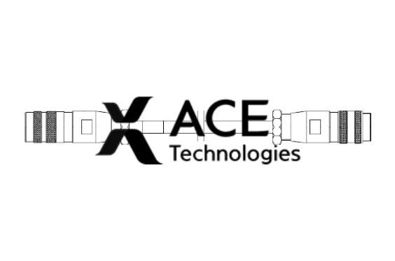
-
AVT-AISGF-AISGM-10.0M
1. Protocol --- AISG2.0/AISG1.1 2. Rated Voltage (max) V 300 Pin Material QSn6.5-0.1Y Gold 3. Rated Impulse Withstand V 1000 Pin Insulator PBT553 (Black) --- 4V.oIlntasguelation Resistance (min) MΩ 500 Connector Body Brass Nickel (3μm) 5. Contact Resistance (Max) MΩ 5 Wire Gauge UL2464 Cable, Black PU --- 6. Current Rating (at 40° C) A 5 7. Test Voltage V AC 670 8. Characteristic Impedance Ω 100 ± 20 -
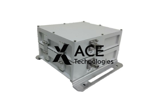
Dual Band Diplexer 0709
- Type : Diplexer
- Frequency Range : Band 1 698~793MHz / Band 2 890~960MHz
- Key feature : Suitable for BTS or antenna end of the feeder, Single or Double Units available for Indoor or Outdoor use
-
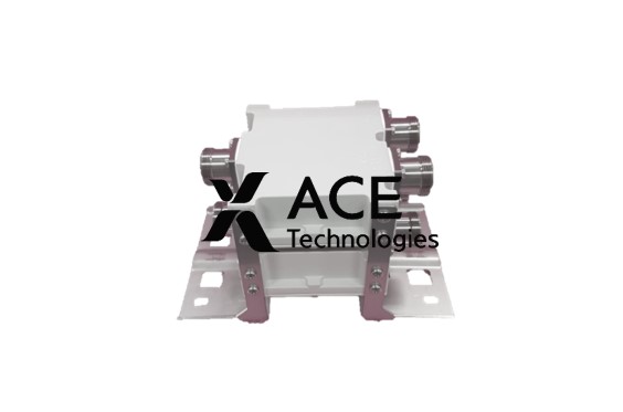
Dual Band Diplexer 1821
- Type : Diplexer
- Frequency Range : Band 1 1710~1880MHz / Band 2 1920~2170MHz
- Key feature : Suitable for BTS or antenna end of the feeder, Single or Double Units available for Indoor or Outdoor use

-
XJ25-B1 R0
- Type : Combiner
- Frequency Range : Band 1 900~960MHz / Band 2 1427.9~1485.9MHz / Band 3 1960~2170MHz / Band 4 2545~2595MHz
- Key feature : 1 In/Out port – 4 Channel, In-door double type filter, Dual band topology
-
XJ25-C1 R0
- Type : Combiner
- Frequency Range : Band 1 1744.9~2170MHz / Band 2 2545~2595MHz
- Key feature : Low Insertion Loss, Compact Size, Low PIMD, DC/AISG Transparency


237, Namdongseo-ro, Namdong-gu, Incheon (Nonhyeon-dong), Republic of Korea | Tel : +82 32 818 5500 | Fax : +82 32 818 5505 | Webmaster@acetech.co.kr
Copyright © 2017-2025 ACE Technologies Corp. All rights reserved.
